Here is another electronic circuit of a driver for Led, this project is identical to the previously published, to Current Regulator for LED High Brightness 1 Watt tipo estrela ( Led Driver). He is part of a series of publications on Led Driver. This driver uses the famous voltage regulator LM317, which in this case is configured as a current regulator orCurrent limiter. This circuit can be easily constructed, low cost and ideal for those with no knowledge of electronics or getting in Hobby.
Here we show a simple detector of electromagnetic radiation to, and which can detect high frequency signals such as cellular phone. I've always been an enthusiast of RF and know their misdeeds health, despite much controversy in electronic media, is impossible to deny that electromagnetic radiation has no effect on the human body.
The Mobile Phone can be dangerous
This statement is a historical fact, it is the first time a global health agency admits publicly that use of mobile phones can cause malignant tumors in the brain. There is a fight that involves billions of dollars on the effects of continued use of the cell phone, on one hand large companies like Motorola, Sony, Google, LG, Aplle among other, and on the other hand medical and health organizations worldwide. information Cell Phones and Cancer Risk - via
A single detector of radio waves
The detector circuit Electromagnetic Radiation of Mobile Phones
Electromagnetic Radiation Detector for Mobile Phones
Here in Brazil nowadays these phones work with the GSM transmission systemwhich is the acronym of “Global System for Mobile Communication ” . O GSM tem 4 frequency bands, que são: 850 MHz, 900 MHz, 1800 MHz e 1900 MHz. Give that talk of Dualband, tri-band and quad-, ie how many bands in the cell operates.
Modern mobile phones are always communicating with the local radio base stations ( antennas or ERBs), this communication is via digital pulses transmitted through radio waves as a Morse code signal extremely fast.
The circuit described in this article is a homemade device manufacturing, low cost, very simple construction, that converts the energy of radio waves (electromagnetic waves ) a cell phone into electricity capable of lighting a single LED. This technique is well known among experts in the field of telecommunication to detect RF signals in coils and is the operating principle of power transmitter.
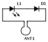
The circuit is composed of 3 connected elements, all in series , the LED ( common or high gloss), germanium diode and a loop antenna or frame. They must be connected correctly, all these components are cheap and readily available in your home scrap.
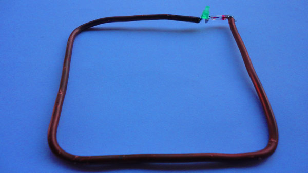
The circuit can be made from a piece of copper wire that will serve as the loop antenna, but can also be done on a printed circuit board. One tip is that this detector SMD components can also be done.
Installation is very simple, just weld the germanium diode and the LED on the loop antenna and ready, always respecting the polarity anode and cathode of the diode and LED as described in the scheme. The circuit works well, the LED and the germanium diode allows current to flow in the same direction, this means that the germanium diode LED and are joined at the cathode and an anode of the other.
When a radio wave passes through a metal object the EM fields cause charged electrons in the metal to oscillate and this causes small AC currents are generated at the same frequency.
If a cell phone is close to the Electromagnetic Radiation Detector circuit and a call or SMS is made, radio waves emitted from mobile phone go through the loop antenna. This induces a voltage in the antenna and if you are near, this will be enough to light the LED.
The size of the loop gain of the antenna circuit influences the, therefore the antenna has a wave length, that for this frequency is not so great, causes but there is a good power transmission between the mobile phone and the LED.
The cell phone always sends a signal (digital pulse) What does the testing of the network and automatically adjusts its transmission power to maximize battery life and minimize interference . Result, The LED brightness will depend on the data to be sent, the intensity of the local signal and the proximity of the circuit cell phone.
List components of Electromagnetic Radiation Detector
D1 – 1N60 Germanium Diode Detector, AO91, 1N34A etc L1 – LED comum ANT1 – Antena loop ( or loop antenna ) full wave for frequency 1 Ghz (see text below)
Building Antenna Electromagnetic Radiation Detector for Mobile Phones
Using Plane Antenna Calculator online terra we can do the calculation based on the frequency of 1Ghz and the result is 71.3mm, that will be multiplied by 4 to have the entire wave that is 285,2mm or 28.5 cm.
We use the base frequency of 1Ghz for being an intermediate frequency standard GSM frequencies, but nothing prevents you from using the exact frequency, If you make sure the frequency used in your region, it can be 850 MHz, 900 MHz, 1800 MHz ou 1900 MHz. The dimensions are not critical.
To build the antenna will use copper wire which may or may not be enamelled or jacketed, this will depend on the preference of the user. Instead of making a circular loop antenna, we do square, eg, with the sides of 7,5 cm each.
A wire thickness is not critical, also is at the discretion of those who build, but it is clear that the thinner the wire, easier it will deform. If the wire is enameled remember to scrape the varnish and tin the ends.
We can also make various loop antennas with different lengths of sides for different frequencies , inclusive 3G e 4G. For this, for example we can use measures of sides 3,7, 7,5, 10,0 cm, etc..
The electric and magnetic fields depending on how they are generated by the transmitting antenna, if the field is parallel to the ground we say the wave is horizontally polarized, while its inverse we say that is vertically polarized.
The antenna loop will respond better to one type of polarization (depending on its orientation), so it's worth experimenting with the orientation of cell (or loop antenna) for the strongest signal, This is, more let bright LED .
Test of Electromagnetic Radiation Detector Cell
Testei detector, well done crudely, with a wire 12 AWG that was played on the counter. Used an LED and an LED recycled, measurements were not exact , +or- 7 cm. Although the LED lights faintly, You can see their operation. To shoot had to use a darker environment since the camera was not picking up the LED flashing in normal lighting.
Radiation Detector
I believe that with an antenna with the staid and measures small changes can have more sensitivity in signal cell.
Other changes in Electromagnetic Radiation Detector
To increase the gain, replace the LED by a capacitor of 100nF disc and in parallel with the capacitor add a DC amplifier . Can also be added at this same point a headset, um multímetro, etc.
Thisisaschema of a 1.5Voltsource,ideal forreplacement ofbatteriesof1.5or1.2Voltsforbench tests,feedcircuits witha battery withmore tensionasthose of9and12Volts,or evenuse as a batteryEliminator.The circuitis simple,it is based on the317regulatorintegrated circuit,ICis adjustedthrough the220and47Ohmresistorsto providea1.52outputVolts.LM317T,CIwas usedwherea heatsinkwas added,can also beuseda batteryinsteadof the fontsandbridge rectifierfromdiodesthatarein the schema. http://www.eletronica.com/fonte-de-alimentacao-1-5-volt-regulada-usando-lm317/